CAD drawings of the burner in different formats are available here.
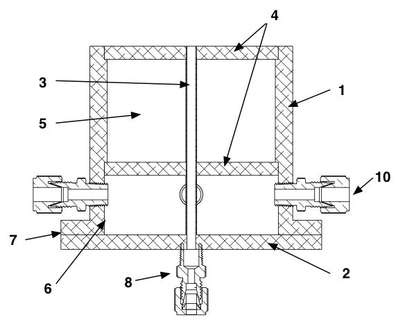
Parts list - included with burner*the number in parenthesis refer to the schematics at the bottom of the parts list.
(2) Bottom Plate
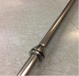
(3) Fuel Tube
(4) Honeycomb:
(6) Screen: supports bottom honeycomb that confines glass beads.
(7) O-Ring: seals Coflow Housing to Bottom Plate.
(8) Fuel Tube Support Fitting:
Parts list - non included with burner
(9) Fuel Tube Connection Fitting
(10) Air Connection Fitting (x4)
(11) Nuts and Bolts (x4):
Assembly instruction:
Assembly
will take place in three sections: coflow housing, bottom
plate, and final assembly. Note: the following pictures show
a plastic 3D printed model of the burner. As specified
above, the actual burner body will be aluminum.
Coflow housing:
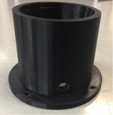
Fig. 1: Coflow housing, as provided.
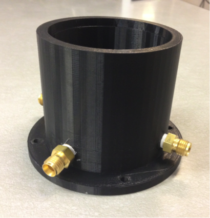
Fig. 2: Coflow housing with fittings inserted.
After inserting all four fittings, the burner should look like Fig. 2.
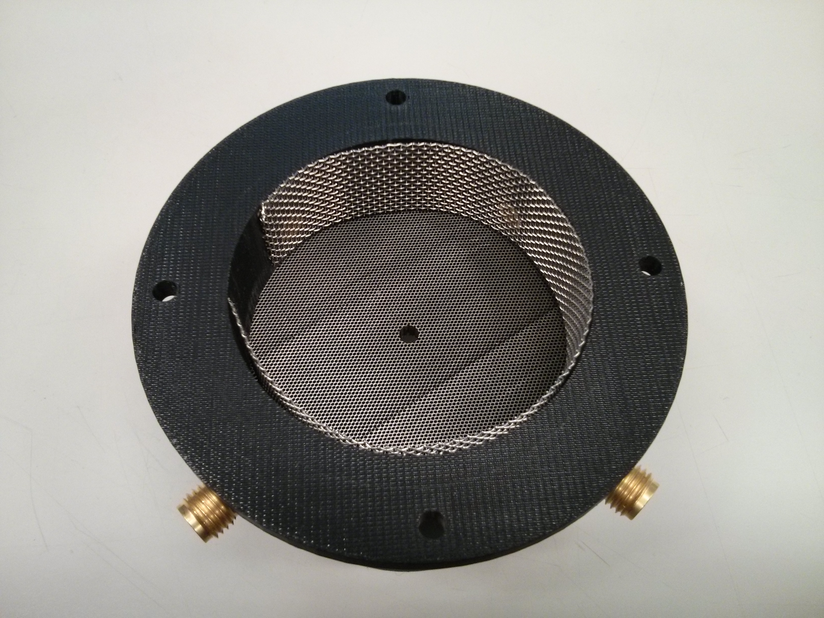
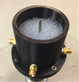
Fig. 3: Coflow housing with mesh and bottom honeycomb.
Bottom
Plate:
The
hole
in the center of the bottom plate is pre-drilled to 0.12.”
This allows for the option to press fit the fuel tube
through the hole. For this assembly guide, we will instead
use a bored-through 1/8” NPT fitting to connect the fuel
tube. This fitting is provided in the kit, as shown in
Figure 4.
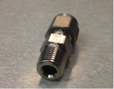
FIg. 4: Bored-through NPT fitting.
Drill
the center hole to 11/32” and tap it. Then screw the fitting
into the hole, as shown in Figure 5.

Fig. 5: Bottom plate with NPT fitting inserted.
Final Assembly:
Place the provided o-ring over the bottom of the coflow housing as shown in Fig. 6. Note: the model shown does not have an o-ring grove, which will be part of the actual burner.
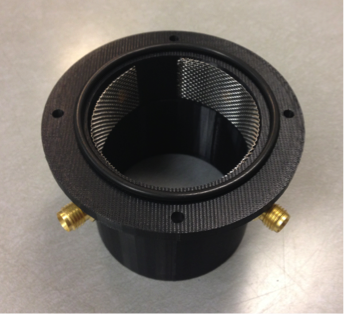
Fig. 6: O-ring placed over coflow housing.
Sandwich the o-ring between the bottom plate and the coflow housing. Use nuts and bolts to secure the two pieces together, as shown in Fig. 7.

Fig. 7: Coflow housing and bottom plate assembled.
Insert the fuel line through the bored-through NPT fitting.
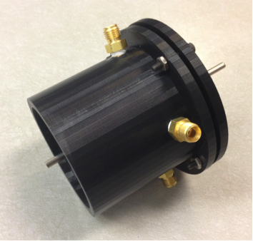
Fig. 8: Fuel tube inserted through bottom plate.
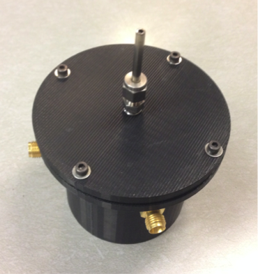
Fig. 9: Fuel tube made flush with burner top.